

Q1) The voltage at the two ends of a line are 132 kV and its reactance is 40 ohms. The capacity of the line is
a) 217.8 MW
b) 251.5 MW
c) 435.6 MW
d) 500 MW
Solution
435.6 MW
CONCEPT
The maximum power transfer capacity of the transmission line is given by
Where,
|Vs| is sending end voltage of transmission line
|Vr| is receiving end voltage of transmission line
X is the series reactance of transmission line
Calculation:
Given
Vs = Vr = 132 kV
X = 40 Ω
The capacity of the line P
P = (132 × 103)2 / 40 = 435.6 MW
Therefore, the capacity of the line is 435.6 MW
Q2) The most economic load on an overhead line is -
a) Greater than natural load
b) Less than natural load
c) Equal to natural load
d) None of these
Solution
Greater than natural load
Economic load dispatch:
- The economic load dispatch means the real and reactive power of the generator varies within certain limits and fulfills the load demand with less fuel cost.
- The economic load dispatch problem involves two separate steps: the unit commitment and the online load dispatch.
- The unit commitment selects that unit that will anticipate the load of the system over the required period at minimum cost.
- In unit commitment, the criterion for the most economical division of load within a plant is that all the units must operate at the same incremental fuel cost.
- The online load dispatch distributes the load among the generating unit which is parallel to the system in such a manner as to reduce the total cost of supplying.
- While supplying power, the most economic load on an overhead line is greater than the natural load.
Q3) The most commonly used method for the protection of three phase feeder is
a) Time graded protection
b) Differential protection
c) Reverse power protection
d) None of these
Solution
Differential relay:
- Differential relay operation depends on the phase difference of two or more electrical quantities.
- It works on the principle of comparison between the phase angle and the magnitude of the same electrical quantities.
- The differential relay is used for the protection of the feeder, large busbars, etc.
Differential protection for feeders consist of
1) Voltage balance differential relay
2) Current balance differential relay
NOTE:-
Generally Translay relay is used for feeder protection
- The translay relay is a differential relay
- The arrangement is similar to overcurrent relay, but the secondary winding is not closed on itself
- These types of relays are used in the feeder protection and the scheme is called Translay scheme
- In this scheme, two such relays are employed at the two ends of feeder as shown in the Fig
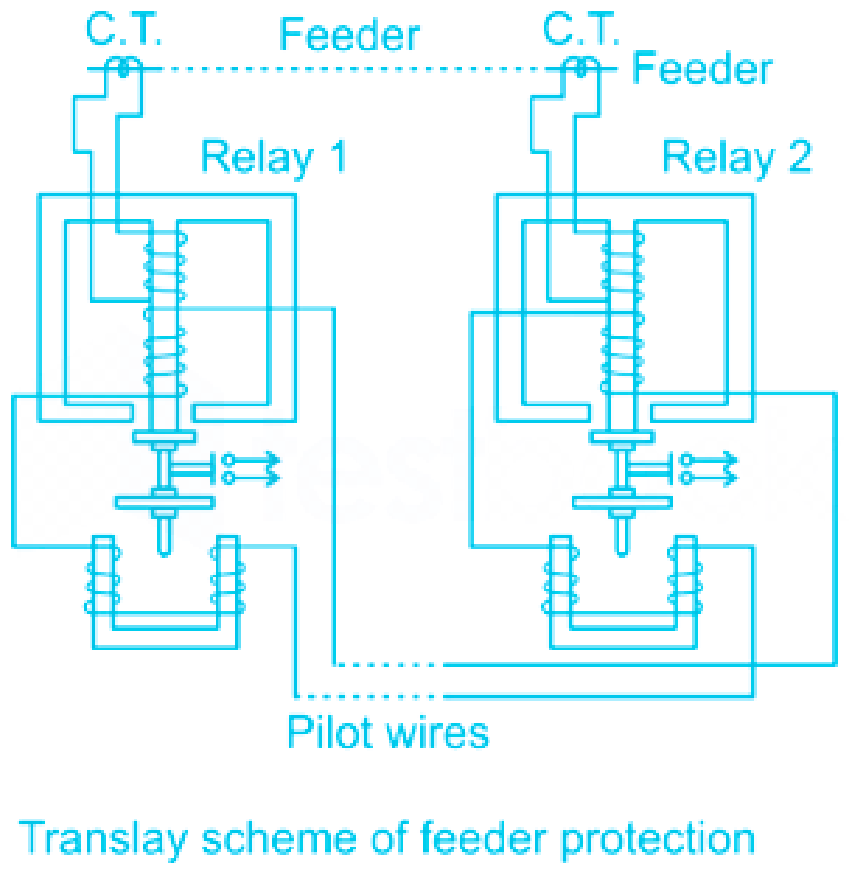
- The secondaries of the two relays are connected to each other using pilot wires
- The connection is such that the voltages induced in the two secondaries oppose each other
- The copper coils are used to compensate the effect of pilot wire capacitance currents and unbalance between two currents transformers
- Under normal operating conditions, the current at the two ends of the feeder is same
- The primaries of the two relays carry the same currents inducing the same voltage in the secondaries
- As these two voltages are in opposition, no current flows through the two secondaries circuits and no torque is exerted on the discs of both the relays
- When the fault occurs, the currents at the two ends of the feeder are different, hence unequal voltages are induced in the secondaries
- Hence the circulating current flows in the secondary circuit causing torque to be exerted on the disc of each relay
- But as the secondaries are in opposition, hence torque in one relay operates to close the trip circuit while in other relay the torque just holds the movement in unoperated position
- The care is taken that at least one relay operates under the fault condition
Q4) Which of the following is NOT correct with reference to delta-star type distribution transformers application?
a) In delta-star type transformer, large, unbalanced loads can be handled without any difficulty.
b) In delta-star type transformer, no distortion is produced by third harmonic components.
c) In delta-star type transformer, secondary voltage is in phase with the primary voltages.
d) In delta-star type transformer, fault protection is one of the primary advantages.
Solution
Types of transformer connections
1.) Delta–Star Connection
- The main use of this connection is to step up the voltage i.e. at the beginning of high tension transmission system.
- The secondary phase voltages lead the primary phase voltages by +30° and this is also the phase relationship between the line voltages.
- Large unbalanced loads can be handled without any difficulty.
- No distortion due to third harmonic components.
- The neutral of the Y-connected secondary circuit is grounded, a load-connected phase-to-neutral or a phase-to-ground fault produces two equal and opposite currents in two phases in the primary circuit without any neutral ground current in the primary circuit.
- Therefore, in contrast with the Y-Y connection, phase-to-ground faults or current unbalance in the secondary circuit will not affect ground protective relaying applied to the primary circuit. This feature enables proper coordination of protective devices and is a very important design consideration.
2.) Star–Delta Connection
- It is used at the load side of distribution systems to step down the voltage levels.
- The secondary phase voltages lead the primary phase voltages by +30° and this is also the phase relationship between the respective line voltages.
- Since the primary winding is star-connected, it requires less number of turns. This makes the star-delta connection economical for large high-voltage step-down transformers.
3.) Star–Star Connection
- These are used for small, high-voltage transformers.
- Because of the star connection, the number of required turns/phase is reduced (as phase voltage in star connection is 1/√3 times of line voltage only). Thus, the amount of insulation required is also reduced.
4.) Delta-Delta Connection
- It is used for large, low-voltage transformers.
- The delta-delta connected transformer is used when neither primary nor secondary requires neutral terminal and the voltages are low and moderate.
Q4) In thermal power plant, the fire tube and water tube boilers are classified based on
a) steam formation rate.
b) the combustion product formation.
c) state of fuel.
d) tubular heating surface.
Solution
Types of boilers in thermal power plant
- In a thermal power plant, fire tube and water tube boilers are classified based on tubular heating surface.
- This classification is based on whether the hot gases pass through the tubes (fire tube) or the water passes through the tubes (water tube) while the combustion gases heat the outside of the tubes.
- Based on the contents of the tubular heating surface, boilers are primarily classified as fire tube boilers and water tube boilers.
1.) Fire tube boilers
- Fire tube boilers are those in which the production of combustion passes through the tubes and water tube boilers are those in which the products of combustion surround the water tubes from outside.
- These boilers operate at moderate pressure (16-20bar) and are more suitable to generate 3-8 tons of steam per hour which is used in process heating.
- Cornish boiler is an example of a fire tube boiler and also includes Cochran, Lancashire, Locomotive, and Scotch marine boilers.
2.) Water tube boilers
- Water tube boilers are those in which the products of combustion (Hot flue gas) surround the water tubes from outside. Cold water enters the tubes and leaves hot.
- These boilers operate at very high pressures and are used for power generation.
- Ex: Babcock-Wilcox boiler, Stirling boiler.

No comments:
Post a Comment